

A hot aisle containment system encloses the server exhaust side and directs hot air toward the cooling equipment’s return-air intake. Air baffles and plenums help control this route: baffles limit unwanted mixing, while the plenum channels exhaust or supply air where it is needed. Leaks around openings can undermine this separation, so performance depends on the airflow path as well as the enclosure.
It is easy to focus on the panels and overlook what happens above and around the racks. This article explains how plenum depth, baffle placement, and sealed openings affect airflow distribution and cooling uniformity. It also compares hot aisle and cold aisle containment, explains when each may suit a facility, and outlines the airflow conditions to assess in a data hall.
Key Takeaways
- Plenum depth affects how evenly air reaches outlets; assess the space and airflow layout together rather than treating depth as a standalone design choice.
- Identify leakage paths around cutouts and interfaces to limit unwanted air movement and strengthen containment performance.
- Use baffles and plenums to keep cool supply air and hot exhaust on their intended routes through the data hall.
- Match hot- or cold-aisle containment to the room configuration, cooling arrangement, and operational use of each aisle.
- Use airflow assessment and Testing, Adjusting & Balancing (TAB) to understand how the installed system performs across the facility.
Ceiling plenum depth and cooling uniformity
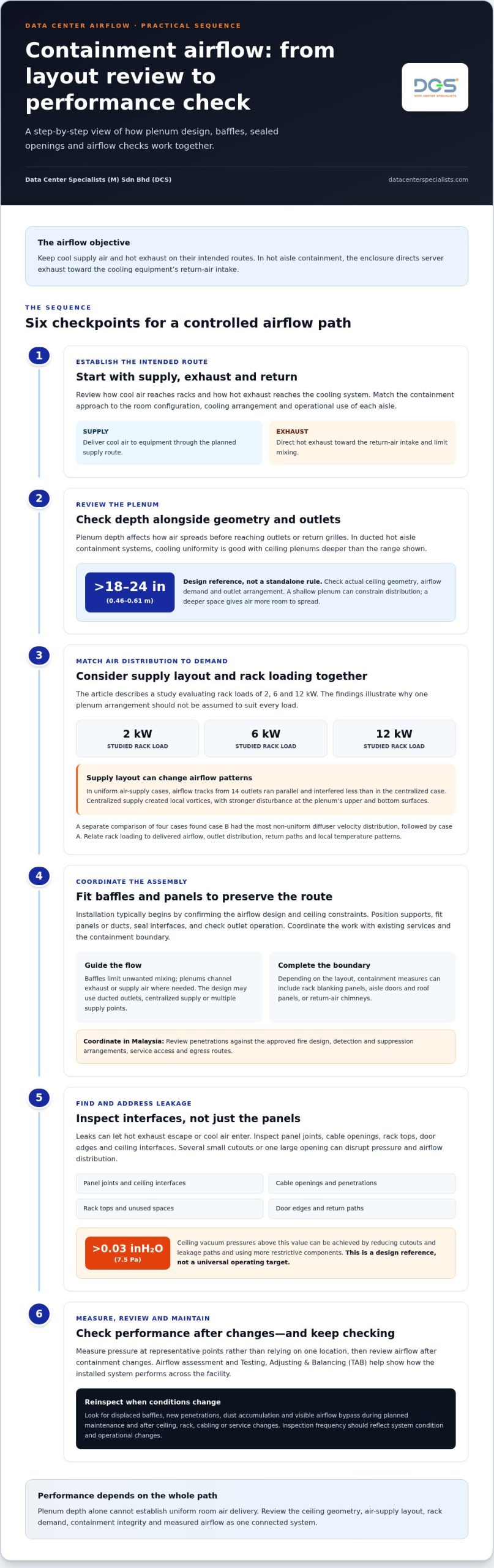
Ceiling plenum depth affects how air spreads before reaching outlets or return grilles. In ducted hot aisle containment systems, cooling uniformity is good with ceiling plenums deeper than 18-24 in (0.46-0.61 m). That range is a useful design reference, not a substitute for checking the actual ceiling geometry, airflow demand, and outlet arrangement. A shallow plenum can constrain distribution, while a deeper space gives air more room to spread.
Air-supply layout also matters. A study comparing four cases found that case B had the most non-uniform diffuser velocity distribution, followed by case A. In uniform air-supply cases, airflow tracks from 14 outlets ran parallel and interfered less than in the centralized case. Centralized supply created local vortices, with stronger disturbance at the plenum’s upper and bottom surfaces. These patterns show why plenum depth alone cannot establish uniform room air delivery.
Plenum and baffle types depend on whether the space distributes supply air or collects hot return air. Designs may use ducted outlets, a centralized feed, or multiple supply points; baffles guide flow and limit mixing between intended air paths. In Malaysia, the project specification should define materials, dimensions, support, sealing, and coordination with ceiling services. Rigid panels or flexible barriers may suit different configurations, but material selection depends on the design and operating conditions.
Cooling coils also respond to return-air conditions. In a data centre with a return-air ceiling plenum, higher return-air temperatures can improve heat exchange across the cooling coil, increasing cooling efficiency and capacity. This depends on directing hot exhaust into the return path instead of allowing it to mix with cold aisle supply air. Assess coil performance alongside temperature distribution and airflow balance.
Rack density changes the airflow requirement. One study evaluated rack loads of 2, 6, and 12 kW, illustrating why a single plenum arrangement cannot be assumed to suit every load. Higher equipment demand requires attention to outlet distribution, return paths, and local temperature patterns. Engineering review should relate rack loading to the cooling system’s delivered airflow, rather than treating ceiling space as an isolated component.
Installation typically begins by confirming the airflow design and ceiling constraints. The team then positions supports, fits panels or ducts, seals interfaces, and checks outlet operation. Coordinate the work with existing services and the containment boundary so the completed assembly preserves its intended supply or return route.
Inspect panels, seals, supports, and openings during planned maintenance and after ceiling or service changes. Look for displaced baffles, new penetrations, dust accumulation, and visible airflow bypass. Inspection frequency should reflect system condition and operational changes. For facilities planning data center containment, these checks help connect physical integrity with measured cooling performance.
Containment airflow leakage prevention
Air leakage weakens aisle containment by letting supply and exhaust air bypass their intended routes. In a hot aisle design, inspect panel joints, cable openings, rack tops, door edges, and ceiling interfaces. Gaps can let hot exhaust escape or cool air enter. The overall leakage pattern matters: a large opening or several small cutouts can disrupt pressure and airflow distribution.
Ceiling vacuum pressures above 0.03 inH2O (7.5 Pa) can be achieved by reducing cutouts and leakage paths and using more restrictive components. Treat that value as a design reference, not a universal operating target. The ability to achieve it depends on the containment boundary, openings, and system airflow. A practical strategy is to map penetrations, seal unnecessary gaps, and measure pressure after changes. Compare readings at representative points rather than relying on one location.
Baffles and plenums guide airflow along a defined route, but they do not replace other containment measures. Rack blanking panels close unused spaces at equipment fronts, while aisle doors and roof panels create a physical enclosure. Return-air chimneys direct exhaust toward cooling equipment. The appropriate combination depends on the data centre layout and how supply air reaches each rack.
In Malaysia, coordinate airflow design with the project’s approved mechanical and fire-safety strategy. Review baffle and plenum penetrations against the building’s fire design, detection and suppression arrangements, service access, and egress routes. Keep airflow openings purposeful, and coordinate modifications with the responsible design and facility teams. This avoids treating a seal or panel change as an isolated task when it affects several building systems.
Poorly designed or installed components can cause bypass airflow, uneven rack intake temperatures, pressure imbalance, and unwanted mixing. Loose panels, unsealed cable openings, and obstructed return paths can also make performance harder to assess. Check the system after installation and whenever racks, cabling, or overhead services change.
- Record openings and interfaces, including rack tops, doors, cable penetrations, and ceiling joints.
- Seal redundant paths while preserving planned airflow, fire-safety systems, and service access.
- Measure pressure at representative points, then review airflow after containment changes.
- Reinspect affected interfaces when rack layouts or overhead services change.
For projects assessing leakage paths across a containment boundary, data center containment provides a relevant framework for reviewing the physical layout and airflow strategy.
Selective delivery of cool air and exhaust of hot air
Hot aisle containment encloses the exhaust side of IT equipment and channels hot air toward the cooling equipment’s return-air intake. This keeps exhaust from mixing directly with supply air around rack intakes. In a ceiling-return arrangement, an overhead plenum can carry collected hot air back toward the air conditioner. Baffles help maintain that route around rack tops and transitions, where air could otherwise escape into the room.
Cold aisle containment serves a different purpose: it encloses the cold-air supply where server intakes are located. In a raised-floor data centre, conditioned air may rise through floor diffusers into the enclosed cold aisle. Racks draw in that supply air and discharge warmer exhaust into the surrounding room or a return path. This approach focuses cooling at the intake side rather than enclosing exhaust.
Choose between hot and cold containment based on the room’s supply and return arrangement, not the aisle name alone. Hot aisle containment may suit slab-floor halls supplied with cool air from a main cooling source, particularly where return air rises toward ceiling grilles. Cold aisle containment is often used with raised floors. Either way, preserve a clear route from the cooling equipment, through the IT equipment, and back to the return.
Colocation facilities can use hot aisle containment selectively for customer aisles. This lets the operator align the enclosure with tenant deployment and growth rather than enclosing every aisle. Where tenants occupy cages and cool air serves the wider room, containing a specific hot aisle can limit mixing between exhaust and incoming cool air. The position of doors, aisle ends, and return openings determines how well that separation works.
A useful design review traces each air path in sequence. Identify where the air conditioner supplies cool air, locate each rack intake and exhaust, then confirm how the containment boundary directs return air to the cooling equipment. For example, a roof panel that blocks a planned return opening can disrupt the route even when the aisle enclosure looks complete.
Selective delivery improves control only when airflow routes remain distinct and the room configuration supports them. Cooling units, rack orientation, supply openings, and return locations all influence performance. Cooling systems typically account for 40% of a data center’s electricity, so airflow management can form part of an energy-efficiency strategy. That figure does not predict savings from a particular containment design; the layout and operating conditions determine the result.
For Malaysian facilities evaluating aisle layouts, data center containment design can be considered alongside the site’s supply and return paths, rack positions, and operating model.
Airflow management and thermal efficiency
Thermal efficiency depends on delivering enough cooling airflow to meet IT equipment demand without excessive bypass. For most cases, ducted cooling airflow should exceed ducted IT airflow by at least 10%. This provides a design margin for distribution losses. Compare measured delivery with equipment airflow requirements, then investigate whether any shortfall comes from the cooling source, duct resistance, or terminal delivery.
Leakier drop ceilings change the calculation for passive ducted racks. In that condition, ducted cooling airflow should exceed ducted IT airflow by 20%. Passive ducting also needs about 8 in (200 mm) of clearance. Restricted space can limit the route and reduce delivery at the rack. Review clearances alongside airflow measurements, particularly after overhead services or rack arrangements change.
Airflow ratios help frame performance checks. A study evaluated cooling-to-IT airflow ratios of 0.8, 1.0, and 1.2. These values represent different relationships between cooling delivery and equipment demand, not universal settings for every facility. Use the ratio as one diagnostic measure, then interpret it with rack loading, temperature readings, and system operating conditions. A ratio alone cannot identify the cause of poor performance.
Measure airflow distribution across the room rather than relying on a single sensor or cooling-unit reading. Compare airflow and temperature at representative rack locations, noting variations between equipment positions. If delivery is uneven, inspect dampers, obstructions, and system changes. Record conditions before and after adjustments to distinguish a local improvement from a broader shift in facility performance.
Cooling units positioned close to racks can reduce the energy needed to move cold supply air. Air movement energy savings from cooling units close to the racks are typically at least 75%. This applies to air movement energy, not total facility electricity. Evaluate fan energy separately from chiller operation and overall cooling performance to avoid overstating the effect.
Use a consistent review process when assessing performance:
- Compare ducted cooling airflow with IT airflow, accounting for ceiling leakage and rack clearance.
- Measure airflow and temperature at representative equipment locations.
- Record system conditions before and after adjustments.
- Review air movement energy separately from total cooling energy.
Containment also shapes how air returns to cooling equipment. Hot aisle containment is designed to direct hot exhaust toward the CRAC unit, which can operate more efficiently when it receives warmer air. It is often used in data centres with return-air ceiling plenums, where hot exhaust rises toward ceiling return grilles. Hot aisle containment can also work with return-air chimney containment at CRAC or CRAH units to direct hotter air to those units.
Integrating ductwork with the containment frame allows the system to manage and direct airflow through hot and cold aisles. Cold-aisle containment typically improves energy efficiency by 30 percent compared with operation without cold-aisle containment. Cold-aisle containment with internal cooling typically improves energy efficiency by 30-40 percent compared with traditional raised-floor cooling without containment. Consider the containment arrangement alongside measured airflow and temperatures when reviewing system performance.
How do air baffles and plenums improve airflow containment and efficiency?
Assess a containment design against its operating assumptions before approving changes. Compare the design drawings with current rack positions, equipment loading, ceiling services, and cooling-unit controls. A layout that suited the original deployment may no longer fit after rack moves or infrastructure upgrades. Record the differences so engineers can assess their effects before modifying panels or ductwork.
Set acceptance criteria before installation or adjustment. Define the intended operating conditions, measurement locations, and required project documentation. Agreeing on these points helps distinguish a completed installation from a system that performs as intended. Keep the design basis and commissioning records available to facility staff for future reviews.
Coordinate containment components with other trades. Cable routes, lighting, fire protection, and maintenance access can affect panel and support placement. Resolve these interfaces during design, then document approved deviations during installation. This reduces unplanned changes that could alter the tested configuration or complicate future maintenance.
After a change, record what moved, why it changed, and what performance observations followed. A clear record provides a useful baseline and helps teams determine whether a later issue began with an equipment change, control adjustment, or physical modification. For a coordinated review of data centre containment, align design decisions with operational needs and documented acceptance criteria.
- Compare the approved design with current room and rack conditions.
- Set project-specific acceptance criteria and measurement locations.
- Coordinate panel layouts with building services and maintenance access.
- Document changes and retain performance records for future reviews.
Panels secured to support curbs create a plenum beneath the ductwork. Treat this space as part of the containment path, not an incidental void. Baffles help define the intended airflow route, while the plenum provides space for that route beneath the ductwork. The components must work together: a panel that does not meet its support or a transition with an unintended opening can weaken the design boundary. Review panels, curbs, baffles, and ductwork as a system. Pay particular attention to joints and changes in direction, where the intended path should remain clear and continuous.
Assess whether the arrangement guides air along the planned route and limits unwanted movement between areas. Consider how it performs under operating conditions, including whether equipment changes or access needs have altered the containment boundary. If the intended path is unclear, document it in the design and installation records so staff can distinguish planned openings from gaps that need attention. The goal is not simply to add panels or baffles, but to preserve controlled airflow in a configuration that can be inspected and maintained. Consistent alignment gives operators a clearer basis for evaluating airflow and deciding whether an adjustment is needed. Record approved changes so later work does not disrupt the intended path.
Data Center Specialists (M) Sdn Bhd (DCS): Professional Data Center ISO Cleaning Services
Data Center Specialists (M) Sdn Bhd (DCS) supports facility teams managing airflow, contamination, and cooling performance in mission-critical environments. Dust in underfloor plenums, on rack surfaces, or around baffles can complicate airflow management and contamination control. DCS provides Professional Data Center ISO Cleaning Services for cleaning data centre environments and equipment areas.
Consider a technical assessment when airflow remains uneven after containment changes or contamination is present near air pathways. Testing, Adjusting & Balancing (TAB) assesses airflow distribution, while a Data Center Energy Assessment examines energy performance. Together, these services help facility teams evaluate the relationship between containment, airflow, and cooling operation.
Contact Data Center Specialists (M) Sdn Bhd (DCS) to discuss a technical assessment or the right service for your facility.
Make the Next Airflow Review Count
Use the next rack deployment, ceiling modification, or cooling-system adjustment as an opportunity to review performance under actual operating conditions. Record the changes, assess their effect on airflow paths, and keep the findings for future planning. This makes air-baffle and plenum design for hot aisle containment part of ongoing facility management, not just a construction decision.
When airflow or energy performance needs closer evaluation, Data Center Specialists (M) Sdn Bhd (DCS) offers Testing, Adjusting & Balancing (TAB), Data Center Energy Assessment, and Professional Data Center ISO Cleaning Services. These services address airflow measurement, energy performance, and physical contamination in mission-critical environments.
Discuss your facility’s requirements with DCS and identify a suitable next step. Contact Data Center Specialists (M) Sdn Bhd (DCS) to arrange a technical discussion and keep your airflow strategy aligned with operational needs.
Frequently Asked Questions
What are air baffles and air plenums in containment airflow systems?
Air baffles are physical panels or barriers, while plenums are bounded cavities within a data centre’s airflow arrangement. Baffles may be rigid panels, flexible curtains, or shaped transitions; plenums may be formed above a ceiling or below a raised floor. Their construction and connections matter: inspect joints, service penetrations, and panel supports for gaps, movement, or interference with maintenance access.
How do you size and position air baffles and plenums for an HVAC system?
Base sizing and placement on documented equipment airflow requirements and the HVAC design, then validate the installed arrangement through measurement. For a retrofit, document existing rack and service locations first. Identify constraints such as beams, cable trays, and fire-protection equipment, then coordinate the proposed layout with relevant facility teams. Commissioning observations can show whether the installed configuration performs as intended under actual operating conditions.
What materials and specifications are used for air baffles and plenums in Malaysia?
Rigid panels or flexible barriers may be used, depending on the design and operating conditions. In Malaysia, project specifications should define materials, dimensions, support, sealing, and coordination with ceiling services.