
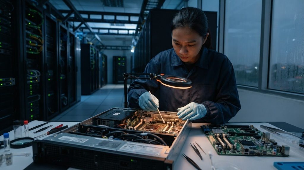
Contamination can be a root cause of server-related electronic failures, not just a sign of an untidy equipment area. The role of contamination in server failure analysis is to establish whether foreign material contributed to the failure, identify its likely source, and distinguish it from other causes such as material defects or structural damage.
A failed component alone rarely explains why a problem occurred. Investigators examine the evidence, compare suspect samples with acceptable materials, and review the component’s service history and environmental exposure. These comparisons help determine whether contamination is relevant and what conclusions the findings support.
This article explains how failure analysis works and how contamination evidence can reveal mechanisms such as corrosion, current leakage, or short circuits. It covers how sample comparisons strengthen an investigation and how findings can inform maintenance improvements. For data center operators in Malaysia, the practical benefit is a clearer basis for deciding whether to focus the response on a component, its operating environment, or contamination control.
Key Takeaways
- Failure analysis connects component symptoms with evidence to distinguish contamination-related damage from other failure mechanisms.
- Compare suspect parts with acceptable or unused materials to assess whether a contaminant is relevant and where it may have originated.
- Use sample history, operating conditions and inspection findings together; contamination alone does not establish root cause.
- Dust, moisture, salt and chemical residues can affect electronic components in different ways, so the investigation should consider the environment as well as the hardware.
- Translate supported findings into targeted maintenance and contamination-control improvements to help prevent recurring issues.
What Is Failure Analysis?
Failure analysis examines a failed electronic component to identify its failure mechanism and likely cause. For server hardware, investigators combine electrical testing, surface inspection, and package examination to guide corrective action.
To see how a structured investigation supports root cause analysis, watch this video:
Failure Analysis for Electronics and Semiconductors
Failure analysis is a structured examination of an electronic or semiconductor component that no longer performs its intended function. It matters because a failed board, package, or connection can result from different mechanisms, each requiring different corrective action. Investigators compare observed damage with design drawings, material specifications, service history, loading conditions, and environmental exposure.
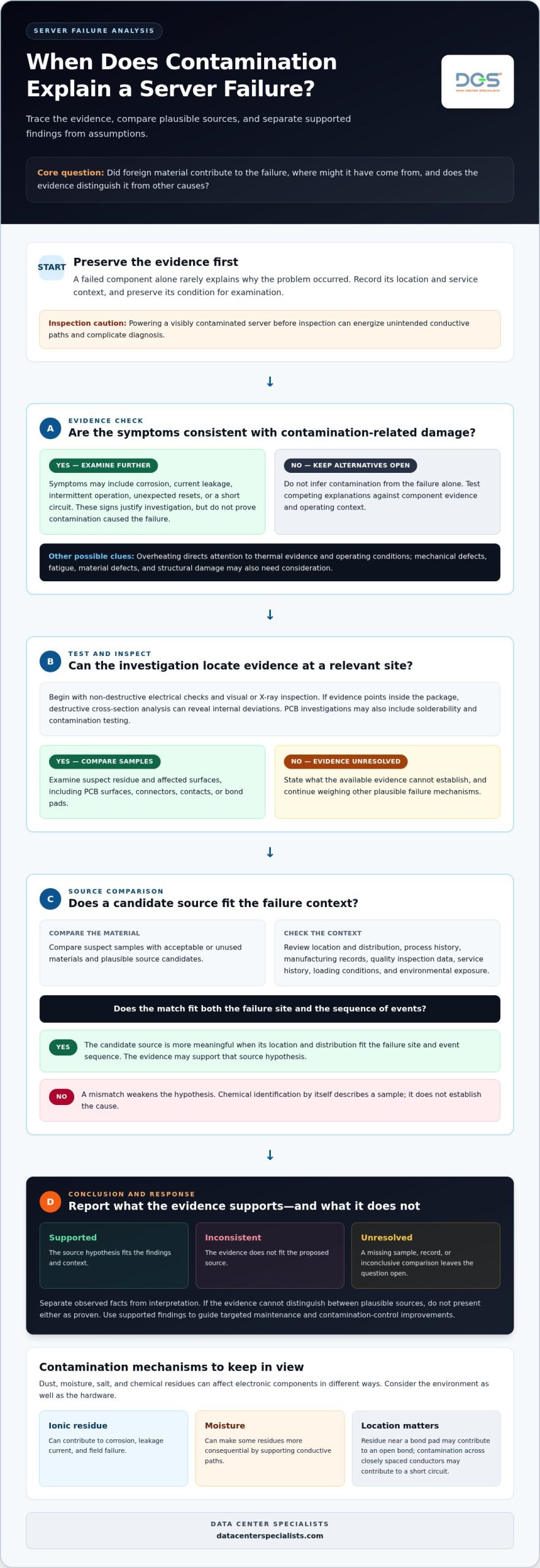
Testing may begin with non-destructive electrical checks and visual or X-ray inspection, preserving the component for further examination. If evidence points inside the package, destructive cross-section analysis can reveal internal deviations. PCB investigations may also include solderability and contamination testing. This sequence helps distinguish contamination from mechanical defects or fatigue, rather than treating every component failure as the same problem.
Contamination-Induced Current Leakage
Contamination-induced current leakage occurs when residue on an electronic surface creates an unintended path for electrical current. Ionic contamination on a PCB can contribute to corrosion, leakage current, and product failure in the field. Moisture can make some residues more consequential by supporting conductive paths between areas that should remain electrically isolated.
Electrical testing can reveal abnormal leakage or unstable performance, while surface and package examination can help locate residue. For example, a contaminant near a bond pad may contribute to an open bond, while contamination across closely spaced conductors may contribute to a short circuit. Understanding contamination’s role in server failure analysis means connecting this evidence to the component’s operating history, not assuming residue alone proves the cause.
Contamination-Related Failure Symptoms and Vulnerable Components
Symptoms may include intermittent operation, unexpected resets, corrosion, current leakage, or a short circuit. These signs can also occur with overheating or other electrical faults, so symptoms alone cannot establish the cause. Overheating directs investigators to thermal evidence and operating conditions; suspected contamination damage calls for close examination of affected surfaces and residues.
PCB surfaces, connectors, contacts, and bond pads are key inspection points because deposits can interfere with electrical connections. Powering a visibly contaminated server before inspection can energize unintended conductive paths and complicate diagnosis. Preserve the failed component’s condition, record its location and service context, then use electrical testing and package examination to determine what evidence supports the next corrective action.
Root cause identification
A root cause investigation tests competing explanations against the component evidence and its process context. Its purpose is to show which causal claims the evidence supports, contradicts, or leaves unresolved.
Investigating Material and Product Failures
Investigators build a causal picture by comparing failure evidence with product, process, and operating records. This matters because a defect can have several plausible origins, each pointing to different corrective action. Relevant context may include manufacturing records, quality inspection data, service history, loading conditions, and environmental exposure.
When investigating a suspected contamination source, compare material from the failed component with plausible source candidates and the process history. A match is more meaningful when its location and distribution fit the failure site and sequence of events. Chemical identification without that contextual fit describes the sample but does not establish the cause.
Root cause analysis also weighs alternative explanations. If evidence suggests a process change, investigators can compare affected and acceptable lots and review records for a shared step or material. If the timing or distribution does not align, the hypothesis weakens. Keeping alternatives in view helps teams avoid settling on the first plausible explanation and overlooking a better-supported cause.
Root-Cause Conclusions and Unresolved Evidence
A defensible conclusion separates observed facts from interpretation and states the status of each source hypothesis. Engineering decisions should reflect both the strength and the limits of the evidence. For example, a report can identify a candidate source as supported, inconsistent with the findings, or unresolved.
Describe unresolved evidence precisely. The report can state which sample or process record is missing, which comparison remains inconclusive, and what follow-up could address the gap. If the available evidence cannot distinguish between two plausible sources, neither should be presented as the proven root cause.
This discipline also makes an investigation useful beyond the immediate incident. A clear record of sample identity, observations, analytical sequence, and limitations helps another technical team understand how the conclusion was reached and which questions remain open.
Failure Analysis and Root Cause Analysis
Failure analysis provides technical evidence about the failed product; root cause analysis evaluates that evidence alongside the conditions that could have produced it. The distinction matters because identifying where a failure occurred does not, by itself, identify its origin. Before assigning responsibility or selecting a control, teams should connect component findings to relevant manufacturing or facility records.
Where an environmental source remains plausible, the investigation can inform a review of contamination pathways around the affected area. For example, findings may justify examining physical controls near equipment or underfloor spaces, including data center contamination-control practices. That review complements the component investigation; it does not substitute for evidence establishing the specific root cause.
Using investigation findings to improve maintenance
Investigation findings are useful when they lead to specific maintenance decisions, inspection priorities, or engineering controls. The response should address the supported failure mechanism, rather than simply repeating the same cleaning or replacement task.
Data center temperature, humidity, and airborne-contaminant limits depend on equipment specifications and facility design. Operators should use those requirements to interpret environmental records and identify conditions that need closer assessment.
Laboratory Investigation of Component Failures
A laboratory investigation examines failed components to connect material evidence with operating or manufacturing conditions. This matters because a fracture, residue, or corrosion feature can point to different maintenance needs. Microscopy, spectroscopy, and elemental analysis help characterize the material and determine its location.
For example, residue identified on a component can be compared with cleaning materials or equipment-contact surfaces. A fracture surface may also reveal a failure pattern that warrants reviewing loading or inspection practices. The investigation should preserve sample identity and record the methods used so engineering teams can relate findings to maintenance history.
Investigation Deliverables and Limitations
A useful investigation report records the samples examined, visible differences, analytical sequence, supported source hypotheses, and unresolved questions. Maintenance decisions need traceable evidence, not just a conclusion. The report should distinguish an identified substance from proof that it caused the failure.
Limitations can arise when samples are damaged, handling history is incomplete, or evidence cannot distinguish between candidate sources. In manufacturing or industrial failures, limited batch records can also constrain comparisons. Clear documentation helps teams decide whether further sampling or analysis is needed before changing a process or inspection plan.
Confirming Contamination as a Failure Cause
Confirmation requires evidence linking a contaminant to the failure mechanism and a plausible source. Finding foreign material alone does not establish causation. Investigators compare the affected component with acceptable material and assess whether the contaminant’s location and properties fit the observed damage.
To investigate a suspected server failure, preserve the failed part and document its location, handling, service conditions, and relevant cleaning history. Compare analytical findings with plausible source candidates, such as process materials or equipment-contact surfaces. If the evidence supports a source, record the connection; if it remains inconclusive, specify the unresolved evidence and targeted follow-up.
Applying Findings to Maintenance
Maintenance improvement translates findings into controls that address the supported cause. This matters because changing an unrelated task can leave the failure pathway intact. If evidence points to contamination entering from a particular area, review that pathway, related inspection points, and the physical contamination-control practices around it.
For a manufacturing batch issue, compare affected and acceptable lots, then review process and cleaning records for shared exposure. For recurring component damage, use the failure mechanism to refine inspection priorities or maintenance intervals. Engineering teams can then track whether the revised approach addresses the identified risk, rather than treating replacement alone as prevention.
Comparison of suspect samples with virgin or acceptable materials
Comparing suspect material with a suitable reference helps determine whether a physical difference is associated with failure. In electronics, useful references may include an acceptable lot, unused process material, cleaning agents, and materials that contact equipment. Comparisons are strongest when each sample has a documented origin and a clear relationship to the failed component or process.
Sampling context matters. Record the failed part’s location, condition, handling, process history, and cleaning history, then identify reference materials that could realistically have contacted it. A sample from an unrelated area may show what is present elsewhere, but it cannot represent the material or conditions directly associated with the failure. Photographs and sampling-location records preserve this context.
Optical and digital microscopy can document surface features, colour, layering, dimensions, and morphology before destructive testing. This baseline lets investigators compare suspect and acceptable samples without losing the initial physical evidence. When appropriate, Raman mapping can compare component distribution, domain size, and relative abundance across products or lots, helping assess whether a material difference aligns with manufacturing variation.
Chemical incompatibility is another possibility to assess when a material has degraded or changed. A valve failure, for example, may involve chemical incompatibility or improper installation. Comparing the affected material with an unused or acceptable counterpart can help identify differences in composition or condition. The comparison should also consider service and process context, since a chemical signature alone does not establish the cause.
Metallurgical examination applies similar comparisons to valve materials. Investigators can assess composition, hardness, and microstructure, then look for corrosion, cracking, or fatigue. This examination can reveal contamination that is not visible to the naked eye. Comparing affected and acceptable areas helps determine whether a material condition is local or more widespread, while relating the finding to the valve’s malfunction.
For server components, choose a reference that matches the failed item in material and relevant process history as closely as practical. Where plausible, compare residue or surface condition with unused process material, equipment-contact materials, and cleaning agents. This narrows source hypotheses and helps distinguish contamination from packaging, material, or manufacturing differences.
Interpret results as comparisons, not verdicts. A visible difference or chemical match can support a hypothesis, but the conclusion must also fit the component damage and available process evidence. If suspect and acceptable samples differ, document exactly what differs and where. If they appear similar, record that finding without treating it as proof that contamination played no role.
What contaminants commonly damage servers, such as dust, moisture, salt, and chemicals?
Dust, moisture, salt-bearing residues, and chemical deposits can affect server components through different pathways. Their impact depends on where they accumulate, whether they contact conductive surfaces, and the component’s operating conditions. In a server room, particles on equipment surfaces and contamination beneath raised floors may indicate different sources, so record location as well as appearance.
Dust and airborne particles
Dust can collect on circuit boards, connectors, fan inlets, and heat-transfer surfaces. Deposits may obstruct airflow or provide a surface where other residues accumulate. For example, a visible layer near a server’s air intake should prompt inspection of the intake path and nearby surfaces, rather than an assumption that the component itself caused the buildup.
Construction work, material movement, or disturbance beneath a raised floor can introduce particles into equipment areas. Investigators can document particle distribution, compare affected and less-affected locations, and examine collected material. This spatial pattern can help distinguish a local source from contamination carried through the room.
Moisture and salt residues
Moisture can make ionic residues more consequential on electronic surfaces. Contaminants combined with moisture may contribute to corrosion, while ionic contamination on a PCB can contribute to leakage current and product failure. Salt-bearing deposits are therefore relevant when corrosion appears near contacts or conductive tracks, but their presence alone does not establish the cause.
Record the residue’s position and the component’s condition before cleaning or handling changes the evidence. Compare suspect material with plausible environmental or process sources, then use suitable chemical analysis to assess its composition. The relationship between residue, moisture exposure, and damage matters more than appearance alone.
Chemical residues
Cleaning agents, adhesives, lubricants, and process materials can leave residues if they contact electronic assemblies. For example, residue on a connector may warrant examination to identify its chemical composition and possible effects on nearby materials. FTIR can help identify organic materials such as polymers, adhesives, and films; SEM-EDX can examine the elemental composition of inorganic particles or corrosion deposits.
These methods address different questions. Microscopy documents where material is located and what it looks like, while chemical analysis helps characterize what it may be. Comparing suspect residues with plausible source candidates supports a more defensible conclusion about their origin and relevance.
Turning contamination evidence into control
Map findings to physical locations, including racks, equipment surfaces, raised floors, and underfloor areas. If deposits cluster near one pathway, investigate that pathway and its maintenance history. A documented data center server room cleaning approach can address physical contamination control while preserving operational requirements.
Keep failed components and residue samples identified and traceable throughout the investigation. Compare visible condition, sampling location, and analytical results before deciding whether dust, moisture, salt, or chemical residue contributed to damage. This disciplined assessment helps distinguish contamination evidence from other possible failure mechanisms.
Data Center Specialists (M) Sdn Bhd (DCS): Professional Data Center ISO Cleaning Services
Data Center Specialists (M) Sdn Bhd (DCS) provides Professional Data Center ISO Cleaning Services for mission-critical environments where physical contamination control matters. The service is relevant when inspections identify particulate buildup, after construction activity, or when maintenance findings point to contamination pathways around equipment.
Cleaning can address equipment areas, rack surfaces, raised floors, and underfloor spaces as part of a controlled facility approach. This helps operators respond to environmental contamination findings while protecting data center operations. Cleaning supports contamination control, but it does not replace component failure analysis when investigators need to establish a specific hardware root cause.
For a data center assessment or technical discussion about contamination control, contact Data Center Specialists (M) Sdn Bhd (DCS).
Turn Failure Evidence Into a Clear Facility Response
Use each investigation to determine a practical next step: establish whether the issue lies with component engineering, environmental conditions, or facility maintenance. Contamination’s role in server failure analysis is most valuable when the evidence leads to a targeted response, rather than a broad assumption about the cause.
For data center operators, a response may involve reviewing physical contamination control, examining energy performance, or assessing airflow balance. Data Center Specialists (M) Sdn Bhd (DCS) offers Professional Data Center ISO Cleaning Services, Data Center Energy Assessment, and Testing, Adjusting & Balancing (TAB) for relevant facility needs. These services support environmental and infrastructure work; they do not replace laboratory analysis of a failed component.
Align the next action with the evidence and the facility’s operational priorities. Contact Data Center Specialists (M) Sdn Bhd (DCS) to discuss a data center assessment or technical service for your facility. A disciplined response can help your team move from investigation findings toward clearer maintenance decisions.
Frequently Asked Questions
How did the failure occur?
Determine how the failure occurred by reconstructing the event sequence from operational records and the affected equipment. Align alarm timestamps, workload changes, maintenance entries, and component test results on a single timeline. For example, compare when a server first reported an error with when a technician recorded a hardware change. This sequence helps distinguish the initiating event from later symptoms and identifies which records deserve closer review.
What RCA Techniques are Typically Used?
Common root cause analysis techniques include fault-tree analysis, cause-and-effect diagrams, and the “Five Whys.” A fault tree maps possible paths to an outcome; a cause-and-effect diagram groups contributing factors, such as process, equipment, or environment. Use these methods to organize hypotheses, then check each against incident records and technical evidence. They structure the investigation, but the findings must support any final causal conclusion.
What can be done to prevent recurrence?
Prevent recurrence by assigning each corrective action to a verified cause, an owner, and a way to assess whether the change worked. For example, if records link repeat incidents to a maintenance step, revise that procedure and review subsequent work for adherence. Track the same operational indicators associated with the original event. If the incident pattern continues, reassess the hypothesis rather than assuming the corrective action was effective.
What is the failure mechanism?
The failure mechanism is the process through which a component loses its intended properties or function. It explains how an initial condition progresses to damage, while the failure mode describes the resulting functional outcome. Investigators use physical examination and material analysis to determine whether a proposed mechanism fits the evidence. Keeping these terms distinct makes technical reports clearer for engineering, operations, and quality teams.
What is the failure mode?
The failure mode is the observable way a component or system fails to perform its intended function. Describe it in operational terms, such as a network interface losing connectivity while the host remains available. This distinguishes the service impact from the underlying physical explanation. Consistent descriptions also help teams classify incident records and compare whether separate events share the same operational signature.
Where is the failure site?
The failure site is the precise location on or within a component where a defect or damage is found. Record it using a board reference, connector position, or package location, and take photographs before further handling. A clear location record helps align laboratory observations with engineering drawings and maintenance notes. It also reduces ambiguity when technical teams discuss the same component during an incident review.
How can contamination cause server hardware failure?
Contamination can impair hardware function when material accumulates at a sensitive interface or changes a component surface. During an investigation, record where the material appears and whether affected units share a location, handling step, or operating history. These comparisons help determine whether contamination is relevant to the incident pattern. Assess the finding alongside the component’s condition and operational evidence.
What standards cover data-center cleanliness and contamination control?
ISO 14644-1 addresses cleanroom air-cleanliness classification, and its relevance depends on the facility specification and assessment scope. It should not be treated as a universal cleanliness limit for every data center. Cleanroom Performance Testing offered by Data Center Specialists (M) Sdn Bhd (DCS) includes ISO 14644-1 classification and particle counting. Operators should define the criteria and measurement approach applicable to their own controlled areas.