

With average rack power densities surging to 27 kW in 2026 according to the AFCOM State of the Data Center Report, simply flooding a data hall with excess chilled air won’t cure localized thermal throttling. If you manage mission-critical facilities, you already know the frustration of watching server fans ramp to maximum speeds while erratic delta-T swings persist across dense rows. Traditional passive measures like basic blanking panels can’t resolve severe intake deficits on their own. Effective high density rack airflow management demands an active, engineered approach that treats cabinet intake velocity, row containment boundaries, and static pressure as an integrated mechanical system.
You can eliminate hot air recirculation, achieve predictable thermal performance across every server chassis, and systematically lower your facility Power Usage Effectiveness without overprovisioning cooling plant capacity. This 2026 guide details the physical dynamics of high-density air movement, containment pressure-balancing protocols, and rigorous mechanical verification practices required to protect operational continuity across dense IT environments.
Key Takeaways
- Master the volumetric CFM requirements and boundary sealing techniques necessary to stop hot air recirculation across dense server tiers.
- Discover why effective high density rack airflow management depends on Testing, Adjusting & Balancing (TAB) to synchronize air delivery with variable server fan speeds.
- Identify how to stabilize aisle differential pressures to eliminate negative pressure zones and turbulent thermal backdrafts.
- Mitigate the hidden risks of accelerated micro-particulate accumulation on dense heatsinks by upholding rigorous ISO 14644 cleanliness thresholds.
- Implement a structured five-phase facility optimization workflow spanning baseline thermal imaging, penetration sealing, and scheduled mechanical verification.
Thermal Dynamics and Airflow Challenges in High-Density Racks
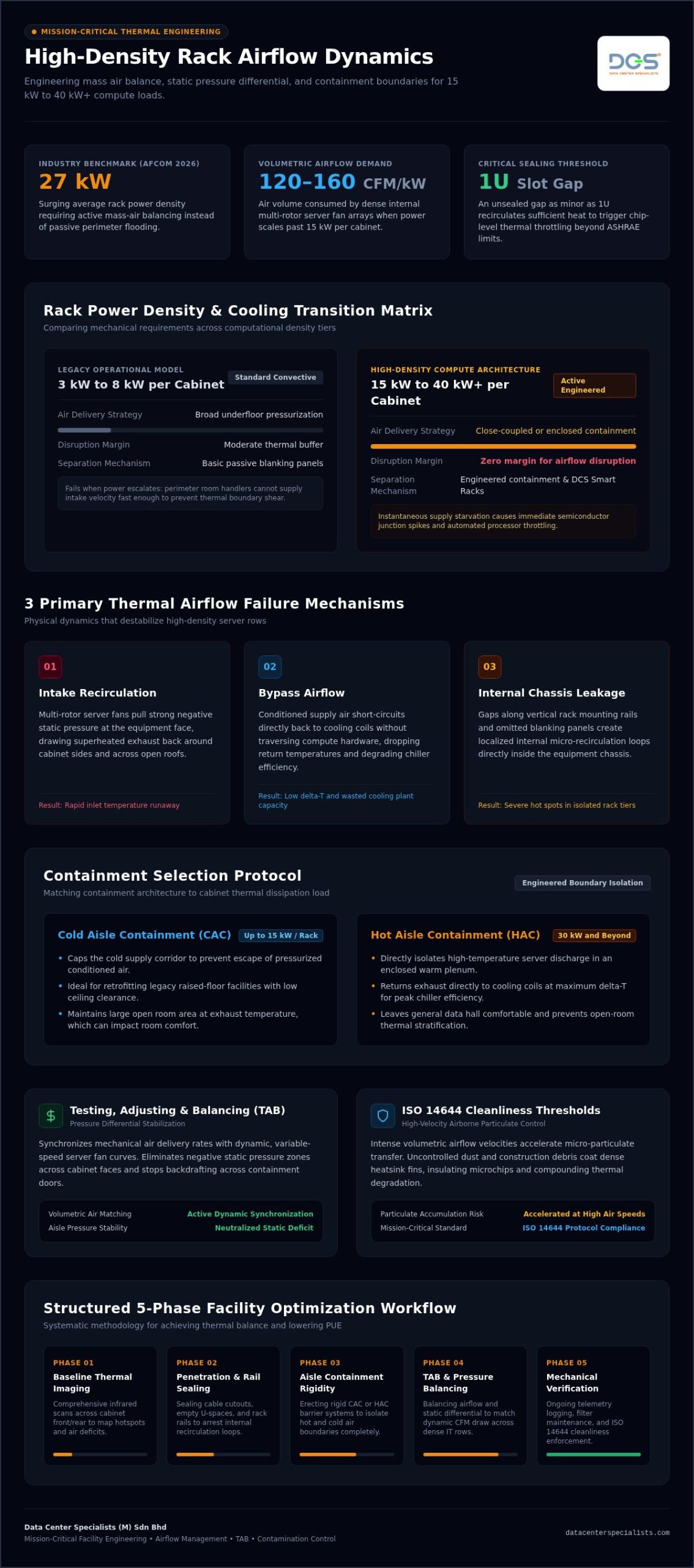
High-density airflow management is fundamentally an exercise in mass air balance and boundary physics. Traditional data halls operating at legacy densities of 3 kW to 8 kW per cabinet relied heavily on convective dispersion and broad underfloor pressurization. In high-density IT environments, that approach fails entirely. When rack power demands climb past 15 kW, internal server fan arrays can draw volumetric flows approaching 120 to 160 cubic feet per minute (CFM) per kilowatt of load. If your mechanical delivery cannot match that precise volumetric rate at the cabinet face, severe static pressure deficits develop within seconds.
These local pressure drops cause extreme velocity shear across the cabinet boundary, pulling superheated exhaust air directly back into cold intakes. To better understand how internal component layout and cabinet mechanics influence this dynamic, watch this helpful video walkthrough:
Defining High-Density Thresholds: 15 kW to 40 kW+ per Cabinet
Modern enterprise compute demands a sharp distinction in thermal management strategies. Cabinets drawing between 15 kW and 40 kW generate concentrated heat fluxes that leave zero margin for airflow disruption. Moments of supply starvation trigger rapid internal junction temperature spikes, pushing chips into thermal throttling. Mitigating these extreme heat profiles often requires transitioning toward integrated row enclosures or specialized close-coupled cooling architectures rather than relying solely on perimeter computer room air handlers (CRAHs).
Mechanisms of Bypass Airflow and Thermal Recirculation
Thermal degradation across dense rows stems from three primary physical failures:
- Intake Recirculation: Powerful multi-rotor server fans generate negative static pressure at the equipment face, drawing discharged exhaust around cabinet sides or over the roof.
- Bypass Airflow: Conditioned supply air bypasses equipment intakes entirely and short-circuits directly back to cooling units, lowering return air temperatures and reducing chiller efficiency.
- Internal Chassis Leakage: Missing blanking plates and unsealed vertical mounting rails create internal recirculation loops inside the rack itself.
Deploying purpose-built cabinet enclosures like DCS Smart Racks establishes continuous physical separation between cold intake and hot exhaust plenums. Without this physical barrier, unsealed gaps as small as a single 1U slot can recirculate enough hot air to raise server inlet temperatures well beyond ASHRAE recommended thresholds.
Core Strategies for High-Density Rack Airflow Optimization
Executing effective high density rack airflow management requires an airtight physical envelope, rigorous isolation architecture, and continuous environmental telemetry. Sealing cabinet boundaries isn’t cosmetic; it dictates whether chilled air reaches high-draw compute chips or spills into unconditioned space. When planning row infrastructure, engineering teams must evaluate three structural pillars to prevent thermal bypassing and ensure uniform intake velocities.
Aisle Containment: Cold Aisle vs Hot Aisle for High Densities
Containment selection depends directly on rack heat load and room ceiling clearance. Cold Aisle Containment (CAC) works well for retrofitting raised-floor environments up to 15 kW per cabinet by capping supply alleys. However, when loads push toward 30 kW and beyond, Hot Aisle Containment (HAC) proves far more efficient. Isolating high-temperature discharge creates an enclosed warm plenum that returns exhaust directly to cooling coils at maximum delta-T, preventing room-level stratification. Integrating engineered solutions such as DCS Containment systems provides the rigid boundary separation needed to maintain stable room ambient conditions across demanding multi-row topologies.
Sealing Floor Cutouts and Internal Rack Leakage Pathways
Unmanaged bypass air often escapes through unnoticed gaps at the cabinet base and rail perimeter. Eliminate these internal leak paths through disciplined hardware sealing:
- Blanking Panels: Install toolless blanking plates across every empty rack unit (U) to block horizontal hot air recirculation.
- Side-Rail Baffles and Foam: Fit vertical air baffle kits along standard 19-inch mounting posts to stop high-pressure exhaust from wrapping back into low-pressure front chambers.
- Cable Cutout Grommets: Deploy dense multi-layer brush grommets around underfloor cable penetrations to preserve static pressure.
- Bottom Rack Skirts: Mount rigid skirting along the cabinet base to bridge the gap between structural casters and the floor surface.
Deploying specialized DCS Smart Racks simplifies this task through integrated cable pathway segregation, full perimeter airflow sealing, and robust mechanical tolerances designed for high-density servers.
Rack-Level Environmental Telemetry and Sensor Placement
Sealing hardware is only half the battle; operations teams also need granular visibility into real-time pressure and temperature gradients. Align with ASHRAE standards by installing intake monitoring triads on each cabinet: one sensor at the top third, one at the midpoint, and one near the base. Pair these with differential pressure transducers mounted across front and rear cabinet faces. Maintaining a slightly positive differential pressure (between 0.01 and 0.02 inches of water column) on server intake faces guarantees that fans draw conditioned air without pulling hot exhaust across boundary seals. If you want to identify lingering micro-leaks in your rows, consider arranging a site assessment with a specialist engineering team to inspect cabinet-level containment integrity.
Mechanical Balancing: Integrating TAB and Pressure Differential Control
Hardware seals and aisle panels isolate airpaths, but they cannot regulate volumetric mass flow on their own. Achieving reliable high density rack airflow management demands active mechanical air balancing. When racks draw intense loads, cooling units must deliver supply air matching server fan consumption curves. Imbalances starve high-density rows or create localized positive backdrafts in low-density sections. Managing these airflow dynamics requires structured engineering protocols rather than guesswork.
Testing, Adjusting, and Balancing (TAB) for Server Inlets
Certified TAB engineers use precision capture hoods, hot-wire anemometers, and micromanometers to measure actual discharge volumes across every perforated tile and supply diffuser. By fine-tuning balancing dampers, technicians route high CFM volumes directly toward dense cabinet faces while trimming excess supply from lightly loaded racks. This mechanical verification aligns delivered cooling with active IT demands. For complete execution workflows and instrument standards, review our specialized technical guide on testing adjusting and balancing data center facilities. Applying these engineering methods eliminates localized turbulence and neutralizes pressure dead zones across contained aisles.
Underfloor Plenum Aerodynamics vs Direct In-Row Cooling
Delivering high airflow volumes through raised floors introduces severe aerodynamic challenges:
- Venturi Effect Depressurization: High-velocity underfloor air streams traveling past perforated tiles convert static pressure into velocity pressure. This dynamic actually pulls room air downward into the floor instead of discharging chilled air upward.
- Plenum Choke Points: Dense cable trays and pipe networks create localized flow restrictions, choking distant high-density cabinets.
- Short-Path Delivery: In-row cooling units circumvent plenum restrictions entirely by mounting heat exchangers directly adjacent to server exhaust points, slashing static resistance.
Plenum depths must provide sufficient cross-sectional area to keep underfloor air velocities below 1,000 feet per minute (FPM). When velocity climbs above that benchmark, pressure stability collapses. Understanding these hydrodynamic principles helps operators decide between retrofitting underfloor delivery or installing row-based close-coupled architectures. Explore our comprehensive analysis on data center airflow management to evaluate how static pressure balancing impacts facility energy profiles.
Contamination Risks and Air Quality at High Airflow Velocities
Engineering a high-volume cooling strategy solves thermal load challenges, but it introduces a severe secondary threat: accelerated contamination transport. As racks consume higher volumetric airflow rates, cabinet intake faces act as giant particulate collectors. Without strict air quality management, massive volumes of circulating air continuously deposit sub-micron particles directly into compact server chassis. Effective high density rack airflow management must account for airborne cleanliness just as strictly as temperature and static pressure.
The Impact of Particulate Accumulation on Server Heat Dissipation
When high intake velocities draw airborne dust across dense server motherboards, debris accumulates rapidly across critical components:
- Thermal Blanketing: Sub-micron particulate films settle between narrow micro-fins and heat pipes, acting as thermal insulation that reduces convective heat dissipation by several degrees.
- Mechanical Fan Stress: Fine abrasive dust infiltrates high-RPM server fan bearings, driving up auxiliary power draw and triggering premature motor failure.
- Electrical Shorting Risks: Zinc whiskers and conductive particulate debris carried by swift air currents can bridge circuit traces, causing catastrophic bridge shorts on dense accelerator boards.
- Electrostatic Build-Up: Non-conductive dust deposits moving rapidly through high-velocity air streams increase localized electrostatic discharge (ESD) risks across exposed electronics.
Maintaining ISO 14644 Cleanliness Standards in High-Density Rooms
ASHRAE TC 9.9 establishes that mission-critical data processing environments should maintain airborne particulate cleanliness consistent with ISO 14644-1 Class 8. In high-density rows, meeting this standard requires proactive source control rather than relying purely on CRAH filtration bank changes. Settled dust in access floor plenums gets picked up by high-velocity airstreams and blasted straight into server intakes.
Preventing hardware degradation requires scheduled environmental decontamination protocols carried out with specialized HEPA-filtered equipment and anti-static extraction techniques. Schedule certified data center cleaning with our engineering specialists to eliminate underfloor particulate reservoirs, control contamination risks, and safeguard your high-density hardware investments.
Implementing a Facility Airflow Optimization and Maintenance Program
Sustaining peak cooling performance requires an operational engineering roadmap. Simply buying blanking plates or sealing cutouts during initial fit-out won’t preserve thermodynamic efficiency as hardware configurations shift. A resilient high density rack airflow management program treats environmental stability as a recurring lifecycle discipline. Facility teams can eliminate emerging hotspots, protect power efficiency, and extend equipment lifespans by executing a structured four-stage optimization framework.
- Step 1: Baseline Auditing: Map spatial intake temperatures and static pressure differentials across every cabinet row under full load conditions.
- Step 2: Passive Envelope Sealing: Close open rack units with blanking panels, install vertical rail baffles, and seal every underfloor cable cutout using multi-layer brush grommets.
- Step 3: Mechanical Containment & TAB: Deploy rigid modular aisle containment and calibrate cooling unit variable-speed drives alongside damper positions via certified TAB engineering.
- Step 4: Continuous Telemetry & Environmental Control: Track real-time delta-T trends, monitor differential pressure across filter media, and enforce ISO cleanroom air quality standards.
Conducting Comprehensive Thermal and Energy Assessments
Pinpointing invisible airflow bypasses requires diagnostic instruments rather than manual walk-throughs. Calibrated thermal imaging reveals subtle cabinet roof recirculation loops, leaky perimeter floor joints, and localized heat stagnation pockets across upper rack tiers. Pairing physical thermal scans with high-resolution Computational Fluid Dynamics (CFD) modeling allows engineers to stress-test row aerodynamics under simulated fan failures or chiller loss scenarios. Commissioning an expert data center energy assessment uncovers stranded cooling capacity, allowing operators to safely raise supply air setpoints and systematically reduce facility PUE. Operators seeking a structured engineering roadmap for reducing energy consumption should also review this technical framework on data center PUE improvement, which outlines how airflow analysis, TAB, and containment work together to drive measurable efficiency gains.
Preventative Maintenance and Periodic Airflow Audits
Operational drift degrades airflow balance over time. IT equipment refreshes frequently dislodge internal blanking plates, unseal floor grommets during cable pulls, or leave unused rack slots exposed. Establishing structured data center maintenance protocols prevents these silent efficiency losses:
- Bi-Monthly Physical Audits: Verify perimeter brush seals, check cabinet blanking completeness, and inspect containment door gaskets for physical wear.
- Filter Static Pressure Checks: Track pressure drops across CRAH filtration media to ensure unobstructed coil face velocities.
- Particle Count Re-Certification: Conduct regular airborne particle counts to ensure high-volume airstreams maintain compliance with ISO 14644-1 Class 8 thresholds.
Partnering with certified mission-critical engineering specialists guarantees that mechanical delivery, environmental cleanliness, and physical containment stay continuously synchronized with evolving server densities.
Mastering Aerodynamic Control Across Next-Generation IT Rows
Meeting the extreme thermal demands of modern computing requires moving far beyond passive perimeter cooling. Realizing predictable server delta-T without thermal throttling hinges on treating high density rack airflow management as an integrated mechanical discipline. By pairing rigid row containment boundaries with professional Testing, Adjusting & Balancing (TAB), facility managers eliminate negative pressure pockets and deliver calibrated volumetric CFM directly to server intakes.
Protecting these dense environments also means actively mitigating contamination risks. High-velocity airstreams accelerate micro-particulate accumulation, making strict adherence to ISO 14644 cleanroom standards essential for preventing heatsink insulation and component degradation. Whether you are deploying engineered DCS Smart Racks and modular containment systems or commissioning comprehensive mechanical balancing, specialized technical oversight ensures that every kilowatt of delivered cooling protects mission-critical availability. Take control of your data hall aerodynamics today: Schedule a Comprehensive Data Center Airflow and Energy Assessment with our engineering team to eliminate hotspots, lower PUE, and maximize your operational uptime.
Frequently Asked Questions
What is the recommended CFM per kilowatt for high-density rack cooling?
High-density air cooling generally requires between 120 and 160 CFM per kilowatt of IT load, depending on server delta-T design targets. Standard server equipment operating across a 20°F to 25°F temperature differential consumes approximately 126 CFM per kW. If equipment operates at tighter thermal margins, airflow delivery must increase accordingly. Maintaining this volumetric supply prevents internal fan throttling and avoids starved chassis intakes.
How do blanking panels improve high-density rack airflow efficiency?
Blanking panels eliminate internal thermal recirculation by physically sealing unused vertical rack units. Without blanking plates, low-pressure zones created by server intake fans pull discharged exhaust from the rear of the cabinet straight through open slots. In high density rack airflow management, leaving even a single 1U slot unsealed can raise adjacent server inlet temperatures by several degrees, triggering premature fan ramping and energy waste.
Is hot aisle containment better than cold aisle containment for high-density servers?
Hot Aisle Containment (HAC) is typically superior for rack densities exceeding 20 kW to 30 kW. While Cold Aisle Containment caps supply alleys effectively, HAC isolates intense exhaust heat within a tight plenum and allows the broader room to serve as a cool ambient buffer. This configuration yields higher return air temperatures directly back to cooling coils, significantly boosting heat exchanger thermodynamic efficiency and chiller operational stability.
Can high-density airflow management eliminate the need for liquid cooling?
Systematic airflow optimization can extend air-cooling feasibility up to roughly 30 kW to 40 kW per cabinet, but it cannot replace liquid cooling for extreme AI architectures. Racks drawing 80 kW to 120 kW exceed the physical volumetric heat-carrying capacity of air alone. However, high density rack airflow management remains vital even in hybrid deployments to cool memory banks, storage arrays, and auxiliary power supplies.
How does air balancing (TAB) resolve localized hotspots in server racks?
Testing, Adjusting & Balancing (TAB) resolves hotspots by mechanically aligning delivered air volume with actual IT consumption. Technicians measure airflow velocity across underfloor grilles and calibrate balancing dampers to redistribute CFM from over-provisioned rows to starved cabinets. This systematic hydrodynamic balancing stabilizes static pressure differentials, eliminating velocity deficits and preventing server fan arrays from pulling hot exhaust across containment borders.
What role does ISO 14644 cleanroom compliance play in high-density airflow?
ISO 14644-1 Class 8 compliance guarantees that high-velocity airflow streams don’t turn into micro-particle conveyors. Dense racks pull massive volumetric air quantities through tight chassis heatsinks. If underfloor plenums and white spaces contain airborne particulates, sub-micron dust deposits rapidly onto cooling fins and circuit boards. This forms an insulating layer that degrades heat rejection, stresses mechanical fan bearings, and risks electrostatic bridging.
What are the primary indicators of bypass airflow in a data hall?
The primary indicator is an artificially low return air temperature entering CRAH units relative to server exhaust temperatures. Other clear signs include elevated server inlet temperatures despite excessive chilled air supply, erratic delta-T readings across cabinet faces, and cold air discharging through unsealed cable cutouts. These symptoms indicate conditioned air is short-circuiting back to cooling coils without absorbing server heat loads.