

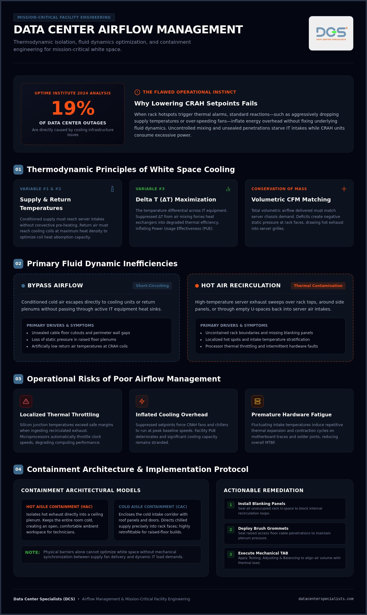
According to a 2024 Uptime Institute analysis, cooling issues cause 19% of data center outages. When persistent rack hotspots trigger thermal throttling, the typical reaction is to lower CRAH setpoints or ramp up supply fans. Yet data center airflow management is an applied fluid dynamics discipline, not a simple thermostat adjustment or an off-the-shelf fix. If bypass air, hot air recirculation, and unsealed floor penetrations starve your cold aisles, running mechanical systems harder only inflates energy overhead without resolving root thermal imbalances.
You already know that uncontrolled operating temperatures compromise hardware reliability and inflate your Power Usage Effectiveness (PUE). In this guide, you’ll master the fundamental engineering principles, containment strategies, and balancing methodologies required to eliminate server hotspots and optimize cooling efficiency. We examine the physical airflow path from supply discharge through the IT chassis to return plenums, detailing how structured diagnostics like Testing, Adjusting & Balancing (TAB) and aisle containment establish predictable thermal envelopes across high-density white space.
Key Takeaways
- Grasp the fluid dynamics governing mission-critical white space to eliminate air bypass and hot air recirculation at the server intake.
- Implement engineered data center airflow management by evaluating the operational trade-offs between Hot Aisle Containment (HAC) and Cold Aisle Containment (CAC).
- Recognize why physical barriers alone fail without systematic Testing, Adjusting & Balancing (TAB) to synchronize supply fan delivery with dynamic IT demands.
- Execute an immediate remediation strategy using targeted blanking panels, brush grommets, and underfloor plenum sealing to curb thermal overhead and lower operational PUE.
What Is Data Center Airflow Management & Why Is It Critical?
At its engineering core, data center airflow management is the thermodynamic isolation of conditioned supply air from high-temperature exhaust plumes. In unmanaged white space, supply and exhaust streams mix uncontrollably. This convective chaos creates unpredictable intake conditions, forcing cooling infrastructure to work harder than necessary. Deterministic air routing replaces this entropy with controlled physical pathways, ensuring chilled air reaches server intakes without pre-heating, while heated exhaust flows directly back to cooling coils.
Precision airflow management centers on three thermodynamic variables: supply temperature, return temperature, and temperature differential (ΔT) across IT equipment. When supply air bypasses the rack plane, return air arrives at Computer Room Air Handler (CRAH) coils cooler than intended. This suppressed Delta T degrades the heat absorption capacity of heat exchangers, elevating Power Usage Effectiveness (PUE). By enforcing disciplined separation aligned with established data center design principles, facility managers can elevate supply setpoints safely, optimize mechanical efficiency, and maximize server Mean Time Between Failures (MTBF).
To visualize how physical containment architecture enforces this separation across operational white space, watch this detailed technical overview:
The Thermodynamic Principles of White Space Cooling
Servers act as convective heat sinks. Internal fans pull air across microprocessors, power supplies, and memory modules, transferring solid-state heat into the moving air stream before expelling it into the exhaust plenum. Under the conservation of mass, total volumetric airflow delivered to the room must match server demand. If air handlers deliver insufficient cubic feet per minute (CFM), negative pressure develops at rack faces, drawing hot exhaust around rack edges. Because air density decreases as temperature rises, hot exhaust naturally stratifies and accumulates near the ceiling, requiring engineered pathways to prevent descent into intake zones.
The Operational Risks of Poor Airflow Management
Neglecting airflow dynamics exposes high-density infrastructure to three severe operational risks:
- Localized Thermal Throttling: Equipment starved of chilled air ingests recirculated exhaust. Processors throttle clock speeds to protect silicon junctions, degrading application performance and creating intermittent hardware faults.
- Inflated Cooling Overhead: Operators often counter localized hotspots by driving supply setpoints down to inefficient levels. This artificial depression forces CRAH units to run fans and chillers at elevated baseline speeds, causing power consumption to skyrocket. Conducting a structured data center energy assessment often reveals that resolving airflow barriers recovers significant stranded cooling capacity.
- Premature Hardware Degradation: Fluctuating intake temperatures induce continuous thermal expansion and contraction cycles on motherboards, fatiguing solder joints and shortening component lifespan.
Primary Airflow Inefficiencies: Air Recirculation and Bypass Air
Thermal waste in technical white space stems from two primary thermodynamic failures: bypass airflow and hot air recirculation. Bypass air occurs when conditioned air short-circuits directly back to cooling units without passing through active IT equipment. Conversely, hot air recirculation happens when high-temperature server exhaust sweeps over rack tops or around side panels, re-entering intake grilles. Both phenomena degrade overall data center airflow management, forcing CRAH units to supply excessive air volumes at depressed setpoints to offset localized overheating.
Mechanisms and Signs of Bypass Airflow
Unsealed cable penetrations and perimeter wall expansion joints act as low-resistance paths that siphon static pressure from raised floor plenums. When conditioned air escapes through unmanaged cutouts, pressure drops beneath perforated tiles positioned in front of high-density cabinets. Misplaced perforated tiles in unpopulated rows or wide transit corridors waste chilled air on empty space. Facility teams auditing these losses can benchmark distribution ratios against metrics outlined in LBNL’s Data Center Energy Efficiency Toolkit. Thermal imaging surveys quickly expose bypass air by identifying low-temperature thermal blooms pooling in return plenums rather than absorbing equipment heat loads.
The Physics of Hot Air Recirculation at the Rack Level
Missing blanking panels within server racks generate internal recirculation loops driven by localized pressure differentials. As chassis fans push air toward the exhaust aisle, low-pressure zones form at open rack units (U-spaces) along the vertical mounting rails. Without physical barriers, hot exhaust reverses direction and gets drawn back through these gaps directly into adjacent server air intakes. A single missing 1U blanking panel can raise intake temperatures by several degrees across adjacent hardware, forcing internal fans to spin up to maximum RPM.
In uncontained aisle environments, top-of-rack and end-of-row boundaries become massive turbulence zones. High-velocity exhaust air spills over cabinet roofs, drawn by the intake depression created by dense server arrays. As rack power densities continue to climb, these recirculation dynamics intensify significantly — a challenge explored in depth in this high density rack airflow management guide for 2026.
Subfloor airflow dynamics also introduce severe contamination risks. Increasing underfloor air velocity to overcome poor pressure distribution mobilizes subfloor debris, concrete dust, and particulate matter. High-speed airstreams transport these abrasives directly into server power supplies and heatsinks, causing micro-arcing and cooling fan failure. Ensuring your underfloor plenum undergoes scheduled data center cleaning maintains strict ISO 14644 cleanliness levels while preventing high-velocity particulate migration across mission-critical white space.
Airflow Containment Architectures: Cold Aisle vs Hot Aisle Systems
Physical containment establishes an engineered boundary that isolates supply and exhaust streams. Instead of relying on open room aerodynamics, modern data center airflow management uses rigid partition assemblies to enforce separation. Choosing between Hot Aisle Containment (HAC) and Cold Aisle Containment (CAC) dictates room thermodynamics, working environments, and fire suppression integration.
| Parameter | Cold Aisle Containment (CAC) | Hot Aisle Containment (HAC) |
|---|---|---|
| Contained Volume | Cold supply aisle (front of racks) | Hot exhaust aisle (rear of racks) |
| Ambient Room Temp | Elevated (room becomes the hot return) | Comfortable (room stays conditioned at supply temp) |
| Coil Return Air Temp | Moderate (some dilution in uncontained space) | High (ducted directly to CRAH coils) |
| Thermal Ride-Through | Limited to small chilled air volume in aisle | Superior; entire open room acts as a cold reservoir |
| Retrofit Complexity | Low; easily integrates with raised floor plenums | Moderate to high; requires ceiling return ductwork |
Cold Aisle Containment (CAC): Mechanics and Application
CAC encloses the supply corridor using roof panels and end-of-row dual-sliding doors, sealing conditioned air delivered through raised floor tiles. It serves as an effective retrofit for legacy facilities with non-ducted, open returns. Because the chilled volume is small, it concentrates cold air precisely where server fans pull it. The operational downside affects human comfort: the broader white space becomes warm exhaust territory, which can compromise working conditions for facility technicians during maintenance tasks.
Hot Aisle Containment (HAC): Thermodynamic Advantages
HAC encloses the exhaust corridor, channeling hot discharge directly into a ceiling plenum return. Maximizing return air temperature significantly increases the sensible cooling capacity of CRAH coils, directly improving chiller efficiency and expanding economizer operating windows. The open room remains fully conditioned, maintaining comfortable working temperatures for operations staff while providing a vast reservoir of chilled air that extends thermal ride-through during mechanical plant interruptions.
Deploying engineered containment requires hardware tailored to dynamic rack densities. Implementing DCS Smart Modular Containment provides scalable ceiling panels and sliding door assemblies that maintain tight seals across varied cabinet heights. When paired with DCS Smart Racks, facility operators achieve precise micro-climate isolation capable of managing both standard compute and high-density clusters.
Mechanical Balancing and Testing: The Role of TAB in Airflow Optimization
Physical containment structures establish the boundaries, but they don’t regulate fluid dynamics on their own. Installing containment without calibrating mechanical delivery can worsen thermal issues by trapping improperly pressurized air streams. Comprehensive data center airflow management requires systematic mechanical calibration to align CRAH fan speeds, plenum pressures, and discharge volumes with real-time IT workloads.
Underfloor Plenum Dynamics and Static Pressure Control
Raised floor plenums behave as pressurized distribution manifolds, yet airflow rarely moves uniformly beneath the tiles. Under the Bernoulli principle, high-velocity air exiting a CRAH discharge nozzle possesses low static pressure and high dynamic pressure. As air travels farther down the plenum and slows against dead-end boundaries, static pressure recovers. Consequently, perforated tiles placed too close to air handlers can suffer from reverse flow, pulling room air downward rather than delivering cooling upward. Regulating static pressure demands precise damper positioning on perforated tiles and subfloor baffles to enforce uniform cubic feet per minute (CFM) output across every rack footprint.
Step-by-Step Protocol for Airflow Testing, Adjusting, and Balancing
Field engineers resolve these hydraulic imbalances through structured Testing, Adjusting & Balancing (TAB) protocols executed across operational white space:
- Baseline Aerodynamic Measurement: Technicians map plenum static pressure gradients with digital manometers and quantify volumetric airflow across every perforated panel using calibrated, zero-backpressure flow hoods.
- Mechanical Damper and VFD Calibration: Engineers adjust variable frequency drives (VFDs) on air handling fans alongside individual tile dampers, matching total air supply strictly to server demand without creating over-pressurization bypass.
- Dynamic Load Profiling: The facility undergoes thermal verification using calibrated sensor arrays under simulated or live compute loads, confirming zero hotspots across server intake planes.
This process follows the engineering framework detailed in our technical guide to testing adjusting and balancing data center facilities. Integrating these aerodynamic diagnostics alongside a comprehensive Data Center Energy Assessment enables facility teams to reclaim lost fan capacity and safely raise baseline chilled water setpoints. Contact our engineering team to schedule professional Testing, Adjusting & Balancing services for your critical facility.
Practical Implementation: Actionable Steps to Optimize Facility Airflow
Remediating airflow inefficiencies in an operational data center requires a structured, phased rollout. Executing physical improvements alongside aerodynamic testing ensures modifications deliver measurable thermal returns. Implementing disciplined data center airflow management involves immediate passive sealing, plenum contamination control, and continuous sensor-driven verification.
Rack-Level Sealing and Passive Airflow Hygiene
Passive containment at the cabinet plane yields immediate thermal improvements at minimal cost. Facility teams should follow these rack hygiene priorities:
- Blanking Panels: Install blanking panels across all unpopulated rack units without exception. Leaving even a 1U gap creates local low-pressure vortexes that ingest exhaust air. For facilities operating above 20 kW per cabinet, review the engineered sealing protocols outlined in this high density rack airflow management guide to address the more severe intake deficits that passive blanking alone cannot resolve.
- Perimeter Air Dams and Brush Strips: Seal gaps between vertical mounting rails and side panels using custom foam baffles. Fit dense brush grommets on all cable entry ports in the roof and floor.
- Cable Management Discipline: Bundle power distribution cords and structured network cabling tightly along cabinet side channels. Unmanaged cable nests behind high-density chassis create massive static backpressure, choking exhaust fan performance.
Environmental Cleanliness and Plenum Contamination Control
Aerodynamic remediation cannot ignore physical hygiene. High-velocity air streams scouring unsealed raised floor plenums dislodge concrete dust, gypsum particles, and zinc whiskers. These contaminants coat heatsinks and thermal sensors, insidiously reducing heat dissipation capacity and skewing temperature readouts. Before adjusting fan speeds or balancing floor dampers, facility operators must thoroughly remediate underfloor spaces. Evaluating critical environments through formal Cleanroom Performance Testing (CPT) verifies compliance with ISO 14644 standards, ensuring airflow optimization doesn’t compromise white space environmental air quality.
Developing a Long-Term Airflow Monitoring Strategy
Thermal management isn’t a one-time project; it requires persistent monitoring. Adhere to ASHRAE guidelines by deploying temperature sensors at the bottom, middle, and top of server intake planes on every third rack. Modern enclosures such as DCS Smart Racks integrate environmental telemetry directly into the frame, providing real-time visibility into localized thermal gradients.
Establish clear operational threshold alerts: an intake temperature spike above ASHRAE recommended limits signals local air starvation, tile misalignment, or unsealed penetrations. When deploying new high-density compute clusters, commission a comprehensive data center PUE improvement assessment to validate that air distribution pathways remain thermodynamically stable and energy efficient as workloads evolve.
Engineer Resilient Thermal Performance Across Your White Space
Achieving predictable thermal boundaries requires moving past temporary fixes. Sustainable data center airflow management demands a coordinated engineering approach: sealing bypass pathways with structured containment, calibrating underfloor aerodynamics through mechanical testing, and safeguarding heat exchangers through strict particulate hygiene. When you align supply fan delivery with real-time IT demand, cooling optimization doesn’t compromise critical hardware reliability, it actively extends component lifespan while lowering operational PUE.
Executing these aerodynamic strategies requires specialized oversight. Backed by mission-critical engineering experience serving facilities across Malaysia since 2008, Data Center Specialists delivers turnkey airflow remediation. Our capabilities unify certified Testing, Adjusting & Balancing (TAB), ISO-standard contamination control, and DCS Smart Infrastructure to eliminate severe hotspots and recover stranded cooling capacity. Consult Data Center Specialists for a professional facility airflow assessment to establish predictable, cost-effective thermal control across your technical white space today.
Frequently Asked Questions
What is the primary difference between hot aisle and cold aisle containment?
The primary difference lies in which thermodynamic boundary is physically isolated from the open room. Cold Aisle Containment (CAC) encloses the supply corridor, leaving the broader white space as a warm return path. Hot Aisle Containment (HAC) traps hot exhaust directly into a ceiling plenum or ducted return. Consequently, HAC keeps the room at comfortable supply temperatures while significantly maximizing return air temperatures and heat exchanger efficiency across cooling coils.
Can blanking panels alone resolve severe server rack hot spots?
No, blanking panels can’t resolve severe hot spots caused by broader hydraulic deficits. Blanking panels only address intra-rack recirculation by preventing hot exhaust from looping back through unpopulated U-spaces. If perforated floor tiles deliver inadequate volumetric airflow, or if underfloor static pressure is unevenly distributed, server intake fans remain starved of cold air. Effective remediation requires coupling rack sealing with subfloor balancing, penetration sealing, and mechanical cooling adjustments.
How does proper data center airflow management reduce PUE?
Proper data center airflow management lowers Power Usage Effectiveness (PUE) by eliminating the mixing of cold supply and hot exhaust streams. Preventing bypass air and recirculation allows facility operators to safely raise chilled water supply temperatures and CRAH setpoints without exceeding ASHRAE thermal thresholds. This setpoint elevation expands economizer hours, decreases chiller compressor workloads, and reduces variable fan speeds, slashing facility parasitic mechanical load relative to the IT load. For a structured engineering roadmap to achieve these gains, review this technical framework for data center PUE improvement covering assessment, TAB, containment, and contamination control.
What role does Testing, Adjusting, and Balancing (TAB) play in airflow optimization?
Testing, Adjusting & Balancing (TAB) calibrates mechanical delivery systems to match actual white-space aerodynamic demands. While physical containment creates boundaries, TAB measures static pressures and volumetric discharge across every perforated tile. Certified technicians adjust fan variable frequency drives, duct dampers, and floor grilles to achieve uniform flow. Without TAB, containment often traps uncalibrated air currents, creating severe pressure imbalances, fan motor strain, and localized cooling deficiencies across server rows.
How does underfloor static pressure affect airflow delivery to perforated tiles?
Underfloor static pressure directly determines the velocity and volume of air discharging through perforated panels. In an underfloor plenum, high discharge velocities from CRAH blowers create low static pressure nearby due to the Bernoulli effect, sometimes pulling air downward through tiles. As velocity slows further down the plenum, static pressure recovers, yielding higher discharge. Regulating static pressure through proper underfloor management ensures consistent cubic feet per minute across all cabinets.
What are the risks of increasing CRAC cooling capacity without managing airflow?
Ramping up cooling capacity without structured data center airflow management inflates operational expenditures while leaving hotspots intact. Unmanaged air bypass simply routes extra chilled air straight back to cooling units, depressing return air temperatures and slashing chiller heat transfer efficiency. In addition, increasing underfloor blower speed creates turbulent air streams that dislodge concrete dust and contaminants, accelerating hardware fouling and risking unexpected downtime without resolving localized thermal starvation.
How frequently should an operational facility perform airflow and thermal assessments?
Facilities should conduct comprehensive airflow and thermal assessments annually, or whenever significant IT hardware deployments alter white-space load profiles. High-density server installations, rack reconfigurations, or cable additions continuously shift aerodynamic resistance and static pressure balances. Periodic audits using calibrated flow hoods, thermal imaging, and pressure sensors verify that existing containment seals remain intact and ensure mechanical supply fans remain precisely synchronized with evolving IT demand.